VOLVO+ Development Story (4), product appearance and PCB design
Before Volvo+, Russia developer already had "Module v2.0" and "Module v4.1". Early version needs to take off interior cover of tailgate, and connects to 5 wires. This module is quite reliable, power-saving and it even has a buzzer to warn people. It's code is quite easy, and don't need to decode CAN bus. It's drawback is harder to install. I don't have confidence to do the mechanical analysis without hurting my car
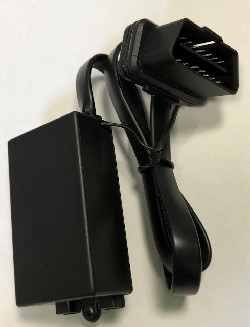
The later product looks like the photo below: an OBD2 connector with a tail to the box
After plugging to OBD2 connector, hide the box somewhere behind handler
I don't like the appearance: it's too big and need to hide the box
My prototype only had 3 ICs, and the realistic size is like ELM327 in the picture below. I took apart the shell, and measured the PCB size within. The PCB size seems to be sufficient to place 3 ICs
The only problem is blue transparent shell doesn't fit the car's style. So I ordered black and white colored shell, it seems to be better
I asked the hardware professional to evaluate the possibility. The answer is possible, it doesn't have high speed signal, and the IC had low pin-count. They even can help me to draw the PCB. I've written ~20 years of FW, and never did the PCB design before, why not try to do it? I used free software KiCAD to do the PCB design
PCB design starts from schematics, which describes how ICs were connected. Then layout designs their real placement on PCB. The software will notify which pins were not connected yet. After connecting all pins, the job is done
As FW programmer, I didn't care about IC package carefully. Now I have to check pin-count, and package carefully. Otherwise, the PCB would be trash.
Doing layout is putting ICs and wires in limited area. The layout requires several iterations to get satisfied result. I even placed two packages for both CAN/Power ICs, which enables me to try more possibilities
I printed the PCB board in actual size, and it seems to match the ELM327 PCB size
Some places to notice
- IC pin definition shall check carefully
- I made mistake in some SOT23 power devices
- OBD2 pin definition
- I made upside-down mistake
That's it, I've decided the product appearance and drawn PCB. I also send the gerber files to make PCB


Comments
Post a Comment