Posts

Showing posts from September, 2020

VOLVO+ Development Story (8), A-SS function definition

Image
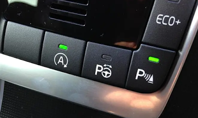
After completing the remote tailgate control function, then I wanted to develop auto start-stop (A-SS) default-off feature. I would like to discuss this feature first Many people don't like A-SS it drained more battery power undoubtedly, used starting motor more times. Many people stopped the feature as engine on. I like this feature really, especially some traffic light with 90 seconds. However, as queuing to turn left/right, the A-SS start latency was sometimes quite annoying I consulted many people, roughly 3 views to this feature Always enable A-SS Always disable A-SS Default A-SS off, and enable A-SS on-demand The Russia developer's product remember the A-SS state as engine off, and remains the status in the next engine start. The logic is fine to the 1st/2nd, but not good for the 3rd one: I shall *remember* to disable A-SS before engine off, which adds more burden Finally, I defined A-SS OFF feature by default. Car owner doesn't remember any rule . As I recalled this,

VOLVO+ Development Story (7), introduce my product

Image
I made the next PCB revision with following changes Remove unused pads Use SMT to mount devices (much better quality than hand soldering) Add my study room (QQM Lab) silk print The product is named "VOLVO+", which adds some feature to the VOLVO car 30 PCB placed together, they're already assembled Make some units with OBD2 connectors Live demo Here's the eBay link

VOLVO+ Development Story (6), sample back

Image
In IC design house, "sample back" means the IC is manufactured from the fab and packaged. This also means starting of high intense verification work. Every time, I would look the IC carefully. Watch its silk print, check size, big or small. The IC carries the team's wisdom and effort ---- My PCB is manufactured by  JLCPCB , the PCB sample backed on 2019/5E. This is the "sample back" event for VOLVO+ I studied the way to solder 48QFP in youtube, and practiced (destroyed) several CPUs. After several rounds of trial, I finally assembled a PCB with all components. Burn the FW and test it on the car. The tailgate closed as expected I made it ! I'm engineer, I make product with profession, and I'm proud of creation

VOLVO+ Development Story (5), low power is HARDER than expected

Image
After the  low power prototype  completed, I put VOLVO+ on my car over night. In the next day, I found the battery voltage dropped deeper than expected. It seems VOLVO+ drained too much current. Measuring low current consumption is not equal to low-power design completed... I put a LED blinking every 0.1 seconds as receiving CAN bus packet. I sit in the driver seat as the car is locked. Several minutes later, the car entered sleep mode but I saw the LED still blinking. The car alarm system detected something moving and triggered the alarm. I can't stop the alarm and finally the OBD2 fuse was broken and I can't do any experiment There are 3 possible reasons that LED blinking as the door locked LED blinking makes car send CAN bus packet The car still sends CAN bus packet, if it enters sleep mode VOLVO+ wakes up the car, so CAN bus packet appeared Repair the car My OBD2 connector lost power because fuse is broken. Although the car is still in warranty, it's probably not good i

VOLVO+ Development Story (4), product appearance and PCB design

Image
Before Volvo+, Russia developer already had "Module v2.0" and "Module v4.1". Early version needs to take off interior cover of tailgate, and connects to 5 wires. This module is quite reliable, power-saving and it even has a buzzer to warn people. It's code is quite easy, and don't need to decode CAN bus. It's drawback is harder to install. I don't have confidence to do the mechanical analysis without hurting my car The later product looks like the photo below: an OBD2 connector with a tail to the box   After plugging to OBD2 connector, hide the box somewhere behind handler I don't like the appearance: it's too big and need to hide the box My prototype only had 3 ICs, and the realistic size is like ELM327 in the picture below. I took apart the shell, and measured the PCB size within. The PCB size seems to be sufficient to place 3 ICs The only problem is blue transparent shell doesn't fit the car's style. So I ordered black and white co

VOLVO+ Development Story (3), prototype

Image
To make VOLVO+, I used some existing boards to assemble. As a personal developer, there's no HW team to do PCB things, even find IC's FAE to solve problem. I struggled to make each components on PCB working The 1st item is MCU board,  Blue Pill , you can find it easily. The processor can run at 72Mhz, with 64K Flash and 20K SRAM. That means plethora resource to waste :-) I have to do some reworking to the board Remove power LED to eliminate unnecessary powers (to make low-power measurement precise) Remove the 5v-to-3.3v LDO in the back of board (I used my own power circuit to power) CAN bus transceiver had 3.3v/5v variant, and it also had distinct low-power performance. Besides, buying IC from China's Taobao is not good idea, I just bought some failure ICs. Here's some ICs that I've tried NXP TJA1050, 5v Microchip MCP2551, 5v TI SN65HVD230, 3.3v TI SN65HVD231, 3.3v Maxim MAX3051, 3.3v Finally I shall convert 12v to 3.3v to power the board. My power consumption is on